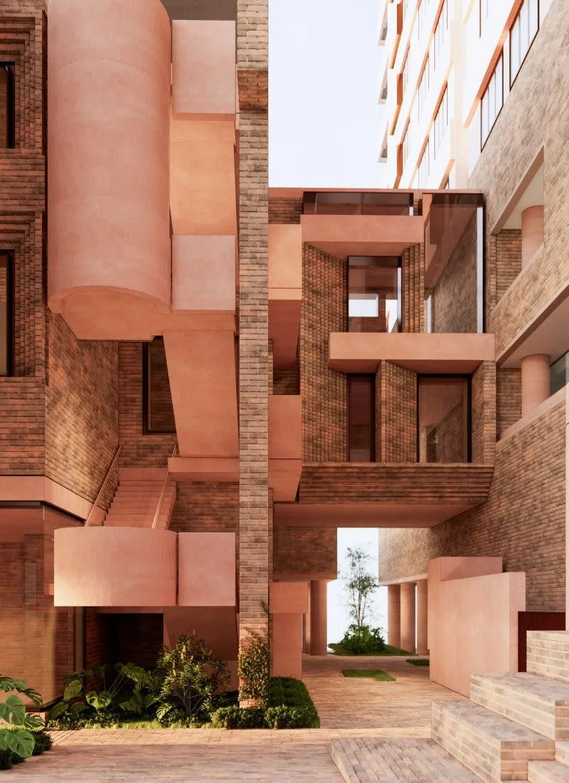
Project name:
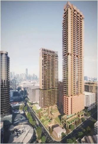
164 Melbourne Street, South Brisbane
Location:
164-170 Melbourne Street & 24-27 Manning Street, South Brisbane, QLD 4101
Building type:
Multiple high-rise towers combining residential apartments, a hotel, and ground-level retail/hospitality
Number of levels:
A three-tower scheme (ranging from 24 to 50 storeys, up to 207 meters high), which includes residential dwellings and a 216-room short-term/luxury hotel
Structural system:
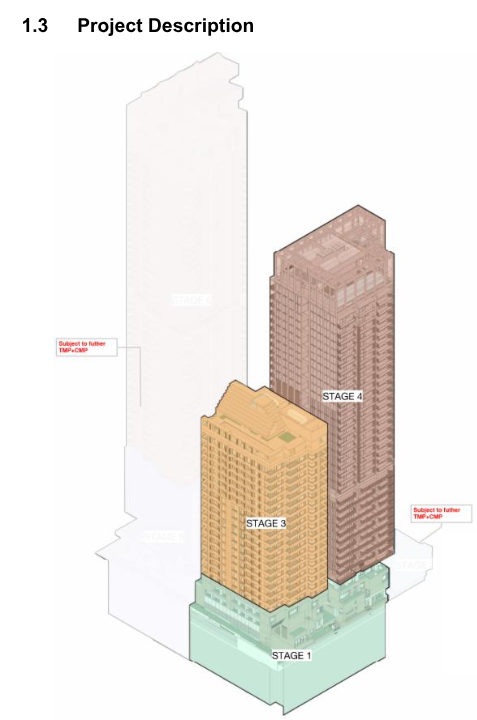
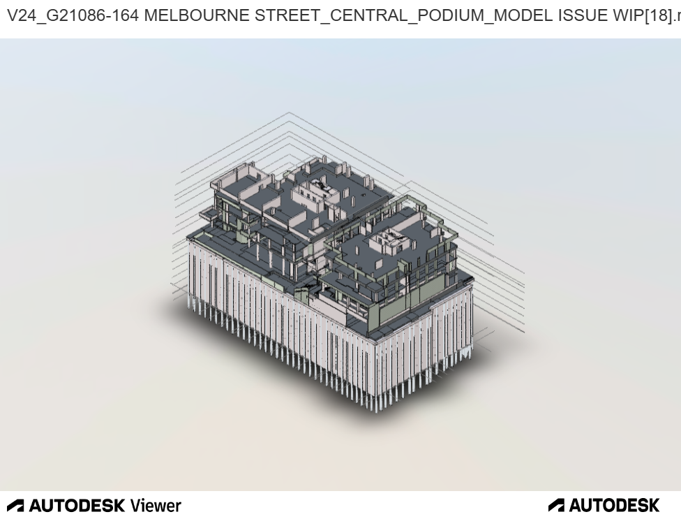
Stage 1 Basement and Podium
Includes partial Basement, podium of Towers A and B
(Indoor sports and recreation, shop, food and drink
outlet, office), comprised of:
a. Basement 07 to 01: Residential carparking
5x levels and Commercial carparking 2x levels, 499
cars;
b. Ground: Cold shell Residential Tower A & B
Lobbies, incl. Loading dock, Fire Control Room, and
Substation. Retail, Commercial, Food and Beverage
(F+B) tenancies, public domain, and precinct laneway;
c. Mezzanine: Cold shell Retail and F+B;
d. Level 02 to 03 (Tower A & B): Cold Shell
Retail;
e. Level 04:
(Tower A) Slab/Staging Roof AHD 20.35m
(Tower B) Cold shell Retail and retail plant;
Stage 3 Tower A Level 04 to 26 Residential Tower
Includes a Multiple dwelling tower, comprised of:
a. Level 04 to 22: Residential, 114x apartments, incl. 38x 2 Beds & 76x 3 Beds;
b. Level 23 and 25: Services/Plant;
c. Level 24: Roof Top Residential facilities/ Amenities;
d. Level 25: Roof/ Lift over-run;
e. Level 26: Lift Motor Room roof;
f. Total height AHD 98.2m.
Stage 4 Tower B Level 05 to 40 Residential Tower
Includes a Multiple dwelling tower, comprised of:
a. Level 5 to 36: Residential, 231x apartments, incl. 18x 1 Beds, 69x 2 Beds, 141x 3 Beds, 2x 4
Beds and 1x 6 Beds;
b. Level 37 and 40: Services/Plant;
c. Level 38 and 39: Residential Roof Top facilities/ Amenities;
d. Level 40: Roof
e. Total height AHD 150.20m.
Services provided:
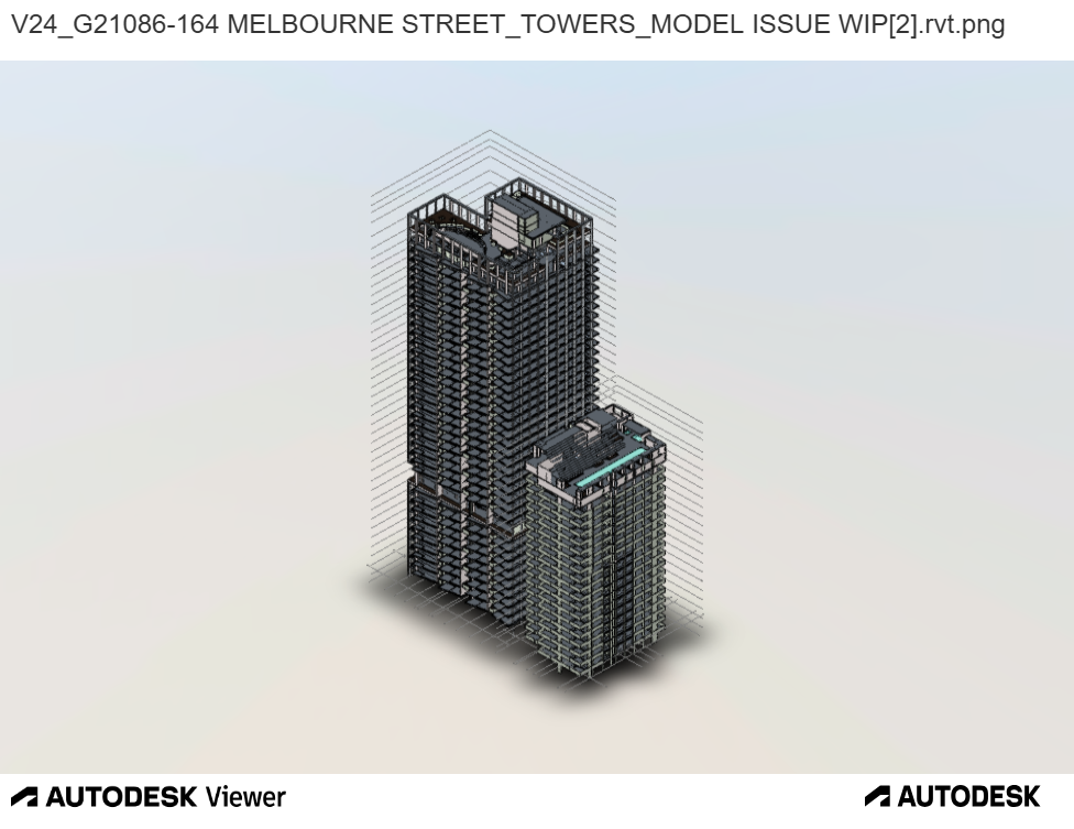
Design and modelling for Stages 1, 3 and 4, comprising:
Determination and specification of applicable load cases and load combinations, including imposed, dead, wind, seismic and construction loads where relevant.
Calculation of load paths and run-down (tributary) load distributions to structural elements.
Finite-element and frame modelling and analysis using RAM Concept and RAPT to verify member actions and slab behaviour.
Development of design solutions for reinforced and post-tensioned concrete and steel members in accordance with applicable codes and project requirements.
Independent spreadsheet-based calculation checks (Excel) validating software results and key design assumptions.
Production of detailed mark-ups and annotations for drafting and documentation of design intent.
Key engineering challenges:
Designing efficient load-transfer systems in multi-storey post-tensioned concrete buildings where complex load paths, differential long-term deformations, and construction sequencing interact.
Why it matters
Incorrectly accounted-for load paths or incompatible deformation behaviour can lead to excessive cracking, serviceability problems (uneven floors, ponding), redistribution of forces that overload secondary elements, and costly remedial works.
Multi-storey and mixed-material structures amplify these risks because stiffness contrasts, differential creep and shrinkage, and variable connection detailing change how loads flow through the structure over time.
Primary factors to address
Complex load paths: transfer of gravity, lateral (wind/seismic) and concentrated loads through slabs, beams, columns, cores and transfer levels; consideration of torsion and eccentricity at setbacks or openings.
Time-dependent behaviour: creep, shrinkage and relaxation in post-tensioned and reinforced concrete affecting long-term camber, stress in tendons and redistribution of moments.
Construction sequencing and staged loading: temporary load cases, propping removal, progressive prestress installation and interaction with partially completed elements.
Differential stiffness and movement: connections between concrete and steel, superstructure over transfer slabs, and transitions between piled and pad foundations.
Serviceability limits: control of deflections, vibration, cracking and water ponding, often governing design more than ultimate capacity.
Detailing and durability: anchorage zones, reinforcement congestion at transfer regions, corrosion protection and maintainability in congested nodes.
Analysis modelling: need for robust 3D finite element models, staged construction analysis, and sensitivity checks to material parameter uncertainty.
Load combinations and robustness: ensuring redundancy so local failures or construction errors do not lead to progressive collapse.
Mitigation strategies
Early integrated design: coordinate architectural openings, mechanical services and façade loads to simplify load paths.
Stage-aware modelling: perform staged construction analyses with realistic creep, shrinkage and tendon relaxation models; check multiple sequencing scenarios.
Conservative serviceability checks: limit deflection and crack widths for long-term performance; design for worst-case losses in post-tensioned systems.
Detailing for transfer: provide adequate reinforcement continuity, dowels and shear transfer mechanisms; avoid excessive congestion; use high-capacity anchors and bearing pads where needed.
Interface design: include movement joints, bearing arrangements and slip-critical connections between different materials to accommodate differential movement.
Quality control in construction: strict control of tendon stressing, concrete curing, tolerances and temporary works; monitoring during construction (deflection and strain) to validate assumptions.
Redundancy and robustness: design alternative load paths, capacity in key members and ductile detailing in potential plastic zones.
Key checks and deliverables
3D structural model with staged construction sequences and time-dependent material properties.
Detailed transfer-level design drawings and reinforcement schedules.
Serviceability report covering long-term deflection, cracking and vibration criteria.
Construction monitoring plan (deflection, tendon losses, strain gauges) and acceptance criteria.
Risk register with sequencing and connection failure modes and mitigation measures.
Outcome objective Achieve a structurally efficient, durable and robust multi-storey post-tensioned building where load transfer and long-term deformations are controlled to meet safety, serviceability and constructability requirements while minimising cost and remedial risk.
Key engineering solutions
Structural concept and system selection
Developed a hybrid structural system to balance span, floor-to-floor height and cost: post-tensioned flat slab for larger open-plan areas, reinforced concrete beams and columns for service cores and stairs, and structural steel framing for long-span/commercial zones.
Optimised load paths and lateral resistance strategy using a combination of reinforced concrete shear cores and braced steel frames where required to meet drift and seismic considerations.
Coordinated early with architect and services engineers to minimise clashes, reduce ceiling voids and avoid excessive slab depths.
Floor systems and slab design
Post-tensioned flat slab design for podium and upper-storey office/retail areas to achieve long spans with reduced slab thickness and smaller drop heights, improving net lettable area and mechanical services integration.
Conventional reinforced concrete slab and beam system for smaller spans and high-load areas (plant rooms, heavy equipment bases).
Design included camber control, deflection criteria, and fatigue checks where dynamic or repetitive loading was expected.
Value outcomes
Reduced overall structural depth and floor-to-floor heights in key areas, increasing usable floor area and lowering façade and service costs.
Construction programme efficiencies through adoption of post-tensioned slabs and prefabricated steel where suitable.
Robust durability and lifecycle performance achieving lower whole-of-life maintenance costs.
Clear documentation and active site support minimised construction risk and change costs.
Selected career experience before establishing ECSEC, this project experience of the senior engineer gained during previous employment. The project was not delivered under the ECSEC appointment.